Tool deformation in JSTAMP: when the die is not as rigid as assumed
A normal forming simulation treats the die as perfectly rigid. A real die deflects under press load. This option brings the die structure into the analysis, so springback is predicted on the die as it really behaves.
What the problem is
During stamping the die carries a very large load, and the die and its supporting structure deflect slightly, by tenths of a millimetre. That sounds small, but it changes the gap between the upper and lower die. The pressure on the part is no longer even: some areas are not pressed fully, others are pressed harder.
The result is that the real part springs back differently from the simulation. The effect grows with high-strength steel such as the 1180 MPa class, because forming it needs a high press load.
Why a normal simulation does not see it
A normal forming simulation uses only the die surfaces and treats them as rigid, called an ideal die here. This is fast and is good enough for most work. But it has no information about how thick the die is, where its ribs are or what it is made of, so it cannot show the effect of deflection.
How the option works
- Run the forming simulation in JSTAMP as usual, with the die surfaces and the blank.
- Combine with the real die structure. The die surfaces are joined to a solid model of the whole die set: upper die (UPR), lower die (LWR), blank holder and base.
- Calculate the deflection and its effect. The deflection of each part of the die is obtained and used in the forming and springback result, so the part is evaluated on the actual die rather than an ideal one.
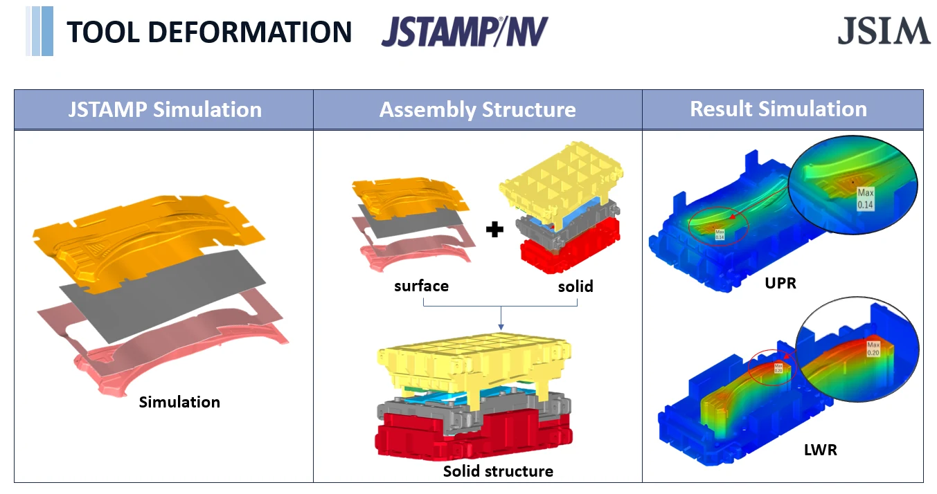
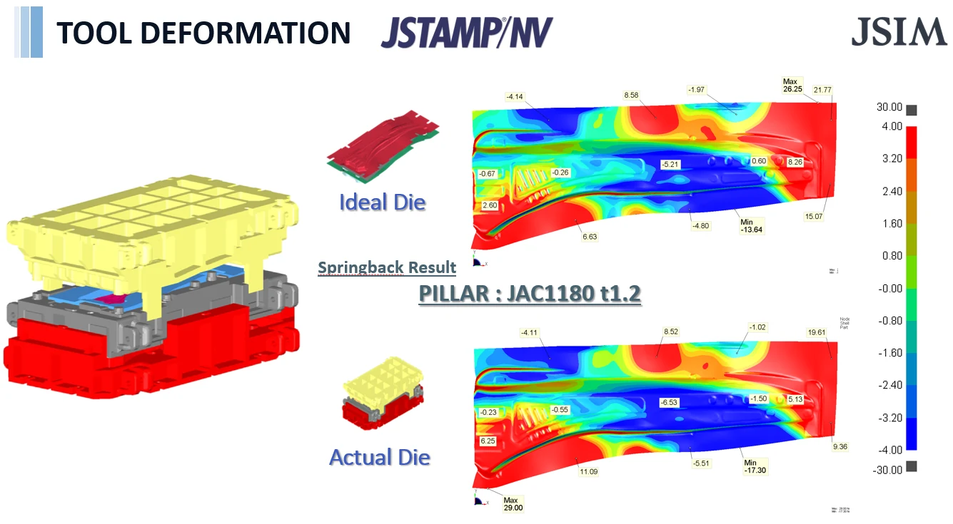
Example: pillar part in JAC1180, 1.2 mm
The slide compares the springback result for the same pillar on an ideal (rigid) die and on the actual die, with values read at the same labelled points.
| Point on the slide | Ideal die | Actual die |
|---|---|---|
| Maximum | 26.25 | 29.00 |
| Minimum | −13.64 | −17.30 |
| Right edge, lower | 15.07 | 9.36 |
| Lower edge, middle | 6.63 | 11.09 |
A second slide shows the deflection of a B-pillar lower die made of FC300 cast iron. The maximum is 0.25 mm, and the deformation has to be scaled 500 times to be visible.
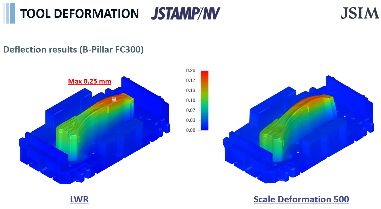
The key point: the die moves by less than 0.3 mm, yet the springback at some points changes by several units on the scale. If the die is compensated using a result that assumes a rigid die, the real part may still miss the target.
When to use it
- High-strength steel parts that need a high press load.
- When the simulation and the tryout part disagree even though the material data is good.
- Before springback compensation, so the compensation is based on how the die really behaves.
- To check whether the die structure is stiff enough, or where it needs more ribs.
Related
- Springback compensation of a 980 MPa pillar part
- Cold stamping 1180-1470 MPa steel
- JESOLVA-Forming: crack prediction option
Source
Examples and figures from JSIM presentation material made with JSTAMP/NV.
Springback that the simulation did not predict?
Send us the part, the steel grade and the die. We can show how die deflection changes the result.