Delayed fracture prediction for press-formed parts
Find the spots on a high-strength steel part that may crack days after forming, using the residual stress and strain left by the forming process.
What delayed fracture is
A part can leave the press looking perfect and still crack later, without any new load. The cause is hydrogen. In a damp or corrosive environment, hydrogen enters the steel and gathers where tensile stress is high. When enough has built up, a crack starts and grows. The time before it appears can be long, so the problem often shows up at the customer, not in the press shop.
Sensitivity rises with steel strength, so the risk grows as parts move to ultra-high-strength grades. The product announcement cites steel in the 1.5 GPa class. Cut edges are a common starting point, and the residual stress that forming leaves in the part is the driving force.
Why it is hard to predict
Nothing is wrong at the end of forming, so an FLD shows no problem and a tryout part looks sound. The risk comes from the stress that stays in the part, which depends on the forming strain and the springback, and from how much stress the steel can carry in the presence of hydrogen.
How JESOLVA evaluates it
- Take the residual state. From the forming analysis, read the forming strain and the residual stress at each point of the part.
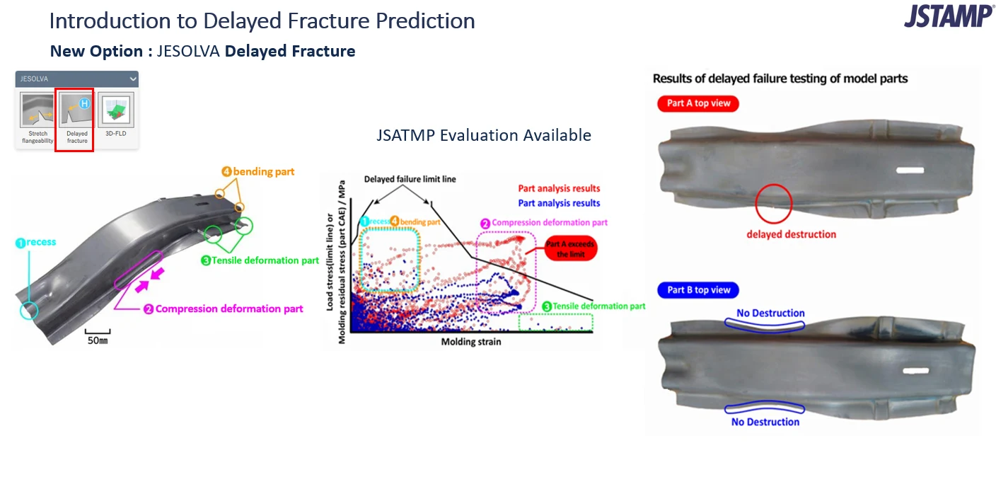
- Plot against the limit. Each point is placed on a chart of stress against forming strain, together with a delayed-failure limit line for the steel.
- Flag what exceeds it. Points above the line are marked on the part, so you can see where the risk is and why.
The slide groups the places where delayed fracture tends to start into four types of region: recesses, compression-deformed areas, tensile-deformed areas and bent areas. Each type forms a recognizable cluster on the chart, which helps in finding what to change.
Example: part A and part B
The slide shows two versions of a model part. On the chart, the analysis points for part A rise to the limit line, and the slide marks that part A exceeds it. The points for part B stay below. In the delayed fracture test, part A cracked at the circled location and part B showed no fracture at the places checked.
The point is not the single result but the ranking: the simulation separated the part that cracked from the one that did not, before any parts were made and left to sit.
When to use it
- Structural parts in ultra-high-strength steel that stay under residual stress in service.
- Comparing two process or die designs for the same part, to pick the one that leaves less critical stress.
- Deciding where to relieve stress, change a bend or edge condition, or choose a different grade.
Other options
- Stretch flange cracking: Cracks at a stretched cut edge, judged with the strain gradient.
- 3D-FLD: Scattered plane-strain cracks in bending, judged with contact pressure.
Sources
Example from the slide above. Background and product details from the JSOL and JFE Steel announcement (Japanese), which describes delayed fracture in corrosive environments under residual stress. The limit values depend on the steel and are set up in the software.
Worried about cracks that appear after forming?
Send us the part and the steel grade. We can show how the delayed fracture check would flag it.