JESOLVA-Forming for JSTAMP: crack prediction beyond FLD
An optional package that evaluates three kinds of cracking a standard forming limit diagram does not capture well, and shows the risky spots in the JSTAMP post-processor.
Why a standard FLD is not always enough
A forming limit diagram (FLD) compares the strain of every element with a limit curve. It works well for cracks that start in the middle of a stretched panel. Ultra-high-strength steel brings three problems it does not handle well: cracks that start at a cut edge, cracks that appear hours or days after forming, and cracks in bent areas where the FLD says the part is safe.
JESOLVA-Forming adds one evaluation for each of these. It was developed by JSOL Corporation, the developer of JSTAMP, together with JFE Steel, and released in April 2026. JFE Steel had used the underlying methods in its own work with automakers, and judged the results by hand before this package existed.
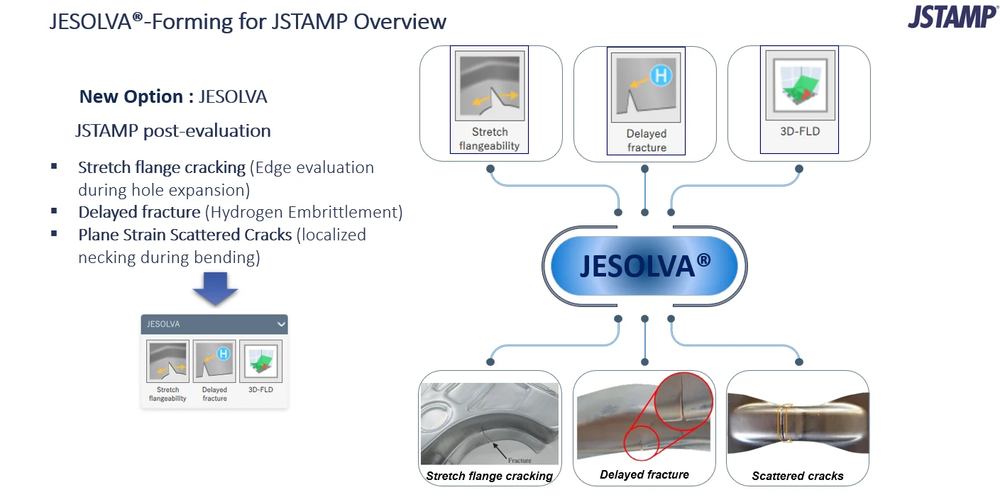
The three options at a glance
| Option | Crack it targets | What it checks |
|---|---|---|
| Stretch flangeability | Cracks at a cut or punched edge that is stretched, such as a hole being expanded | Edge strain and how fast it falls away from the edge, against a material limit |
| Delayed fracture | Cracks that appear after forming, driven by hydrogen and residual stress | Residual stress and forming strain at each point, against a delayed-fracture limit line |
| 3D-FLD | Scattered cracks in plane-strain, bent areas that a 2D FLD calls safe | Plastic strain, strain ratio and contact pressure against a forming limit surface |
Stretch flange cracking
Cracks at a stretched cut edge, judged with the strain gradient.
Read more →Delayed fracture
Hydrogen-related cracks that appear after forming, judged from residual stress.
Read more →3D-FLD
Scattered plane-strain cracks in bending, judged with contact pressure.
Read more →How it fits into a JSTAMP workflow
- Run the forming analysis in JSTAMP as usual, with the material data for the steel you use.
- Open the result in the post-processor and pick the JESOLVA tool for the crack type you are worried about.
- Read the colored result on the part, find the elements that exceed the limit, and decide whether to change the die, the process or the material.
The material and process still have to be modeled well. A crack evaluation is only as good as the strain and stress it reads, so material models such as Yoshida-Uemori and springback setup matter here too.
Who benefits
- Die engineers who need to judge crack risk on 780 MPa and higher steels before tryout.
- Material and body engineers comparing candidate steels for a part, since the edge and delayed-fracture checks are material specific.
- Teams that today decide these cases by experience or by repeated physical trials.
Sources
Product facts from the JSOL and JFE Steel announcement of April 22, 2026 (PR TIMES, in Japanese) and from the slides above. JESOLVA and JSTAMP are registered trademarks of their respective owners.
Want to see JESOLVA-Forming on your part?
Tell us the part, the steel grade and the crack you see in tryout, and a JSIM engineer will advise which option fits.