Stretch flange cracking prediction in JSTAMP
Predict cracks at a stretched edge, such as an expanded hole or a curved flange, by reading both the edge strain and how quickly it falls away from the edge.
What stretch flange cracking is
A stretch flange forms when the edge of a sheet is pulled longer as the flange is raised, for example when a hole is expanded or a curved flange is formed along a blanked edge. Cracks start at that edge and run into the part. Because the edge was cut or punched, it already carries shear damage, so it cracks at lower strain than the same steel in the middle of the sheet.
This is a common failure in 590 MPa and higher steels. A steel can pass a normal tensile test with good elongation and still crack at the edge, which is why edge ductility is measured separately, usually with a hole expansion test that reports the hole expansion ratio λ.
Why FLD does not predict it well
An FLD judges strain in the surface of the sheet. At a cut edge the limit depends on the edge condition and on the steel, and the strain falls steeply with distance from the edge. A point-by-point FLD check cannot tell a sharp strain peak that the material survives from a broad one that it does not.
How JESOLVA evaluates it
- Read the edge strain. After the forming analysis, take the maximum principal strain along the edge, in the circumferential direction.
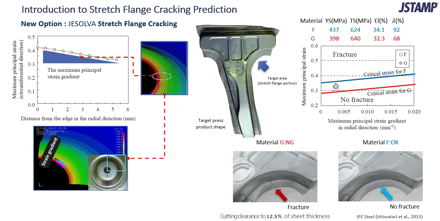
- Measure the gradient. Find how fast that strain drops moving inward from the edge in the radial direction. In the slide, it falls from about 0.42 at the edge to about 0.32 at 5 mm.
- Compare with the material limit. Each steel has a critical strain that rises with the strain gradient: a steeper gradient lets the edge take more strain. The point is plotted against that line, and a point above it is predicted to crack.
The method uses the strain gradient as its index. It received the Japan Society for Technology of Plasticity Technology Development Award for fiscal 2017.
Example: two steels, one part
The slide compares two steels on the same part with the cutting clearance set to 12.5% of the sheet thickness. Steel G has the higher tensile strength and almost the same elongation, but a much lower hole expansion ratio.
| Steel | YS (MPa) | TS (MPa) | El (%) | λ (%) |
|---|---|---|---|---|
| F | 437 | 624 | 34.1 | 92 |
| G | 398 | 640 | 32.3 | 68 |
Elongation differs by under two points, yet λ differs by 24 points. On the chart, the point for G sits above its critical-strain line and the point for F sits below its own line. The tryout part agrees: steel G fractured at the flange and steel F did not.
The lesson is that tensile properties alone would not have separated these steels. Edge behavior needs its own check, and the strain gradient is what links the simulation to the material.
When to use it
- Parts with hole flanges, curved flanges or other stretched edges in high-strength steel.
- Choosing between steel grades or suppliers for an edge-critical part.
- Deciding whether to change the cutting clearance or edge condition, or to reshape the flange.
Other options
- Delayed fracture: Hydrogen-related cracks that appear after forming, judged from residual stress.
- 3D-FLD: Scattered plane-strain cracks in bending, judged with contact pressure.
Sources
Example and data from the slide above, attributed on it to JFE Steel (Ishiwatari et al., 2013). Award and product details from the JSOL and JFE Steel announcement (Japanese).
Cracking at the edge of a flange?
Send us the part and the steel grade. We can show how the stretch flange check would rank it.